Many automobile components — e.g. for engine, powertrain and chassis — are high-performance parts with special requirements concerning mechanical properties and quality. They are commonly produced by forging. Quality standards for these parts are constantly increasing.
Thus, forged products and forging processes have to fulfill rising requirements. Additionally, the globalization of economic life has intensified the suppliers’ competition. The increasing prices for energy and steel cause a rising need to reduce these cost factors. Besides savings, another target is to meet the public concern for ecologic compliance, e. g. reduction of energy and material.
Process Chain
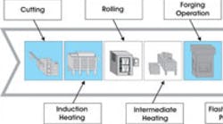
Forgings are produced in several process steps. This process chain begins with cutting and heating of the billet, followed by the forming operations, and it ends with final treatments like flash removal, punching and cooling (see Figure 1). The usual forming operations are preforming and die forging. The preforming can be done by rolling or die forging.
Forging is a shaping process. The two major technologies are conventional forging in open dies – with flash – and flashless forging in closed dies. A hybrid of these technologies is the forging in partially closed dies, where the material flow is restricted in some directions and free in other ones. Intermediate goods produced with this technology are most often flashless [Beh08, Mue08].
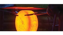
The majority of parts made of steels are hot forged at temperatures between 1,000°C and 1,300°C. The main disadvantage of this temperature level is the development of scale. It leads to bad surface qualities and a waste of valuable material. Additionally, scale exerts a negative influence on the durability of the tools. On the other side of the temperature range is cold forging.
Cold forging is forming of massive steel parts without heating of the workpiece. The main advantages are a good surface quality, due to an absence of scale, closer tolerances, and a decreased energy demand. The main disadvantages are that press forces are necessarily high and that complex geometries like long flat pieces cannot be produced due to high stresses and the resulting die wear. This can be avoided by raising the temperature of the workpiece, up to the maximum point where scale develops. This is called warm forging [ICF01].
Therefore, warm forging is an economical alternative to conventional hot forging technology. There are numerous definitions for the warm forging process of steel. They have in common that the temperature range is considered to be approximately 600°C to 900°C. The lower limit of the temperature range is given by a significant increase of flow stress and a decrease of formability of material [Gei03, Hus03]. Warm forging processes offer the following advantages:
• Closer tolerances, improving the material utilization and decreasing the allowances for subsequent machining operations;
• Reduced surface roughness;
• no scale and reduced decarburization improving the product quality; and,
• Reduced energy demand.
None of the three competing forming technologies (cold, warm and hot forging) is generally superior to the others. Depending on desired part geometry, material, production quantity and accuracy, the most suitable technology has to be chosen. The major benefit of warm forging compared to hot forging is higher accuracy. By combining a warm forging process with a final cold coining operation, IT classes of IT 9 (and in special cases of IT 8) can be achieved [Klo10].
To describe the shape range that can be produced, it needs to be added that most of the geometries that are currently warm forged are rotational symmetric. Until the European research project “DeSProCh – Design of a Semi-hot Process Chain” was finished, other more complex part geometries like long flat pieces had not been manufactured with this technology [Beh08]. Steering links and connecting rods are two representative long flat pieces that are commonly hot forged.
The conventional hot forging sequence of the steering link starts with a cross wedge rolling operation that provides the necessary mass distribution. The rolled intermediate workpiece is transferred to the forging press and a cross-section is preformed in a closed die, followed by a closed-die final forming operation. As a first step, only the forging in dies was developed. Within the DeSProCh project, production lines were set up for the two mentioned long flat pieces (see Figure 2), the forging of these parts was investigated, and a guideline for the introduction of the warm forging technology has been derived [Beh08, Rei07, Rei06].
The material utilization achieved with the steering link forging process is 86%. This is higher than for common hot forging processes, which range from 60 to 80% material utilization. The material utilization obtained for the connecting rod forging process is about 80% [Beh08]. Although the project’s achievements exceeded previous expectations, potential for further improvement was identified:
• comparably low production output due to the high number of operations in the press, and thus a low production rate;
• High development effort for the preforming operations in the press;
• Limitation of the mass deviation along the longitudinal axis; and, therefore,
• Limitation of producible workpiece geometries by the developed warm die forging processes.
The more the mass distribution varies along the longitudinal axis, the more forging operations are necessary, as the tool material can only withstand limited loads. Also, additional forming operations cause a negative impact on the achievable tolerances. Here, rolling operations are a suitable alternative, because they allow a wider mass distribution. Therefore, the rolling as preforming operation in the warm temperature field is investigated as a next step.
Cross Wedge Rolling
Cross wedge rolling (CWR) is a metal processing technique for plastic deformation of a cylindrical billet into an axis symmetrical part, using two rollers that are moving tangentially relative to the workpiece’s main axis. Wedges are the shaping elements on the rollers. Shafts with tapers, steps, shoulders and walls with almost no draft can be produced using the CWR technique [Li08, Pat03].
CWR processes offer several innovative and unique features over traditional machining, forging, and casting operations. These include:
• Higher productivity;
• Higher material utilization;
• better product quality;
• improved environmental conditions;
• Lower operating costs; and
• Less energy consumption.
Despite these advantages, the CWR process has not been widely accepted throughout the manufacturing community [Wan06]. This can be attributed mainly to complexities involved in CWR tool design. The design of CWR tools is difficult because of potential failure mechanisms that can be encountered during CWR process.
Forge Rolling
Forge Rolling (FR) is a forming process for reducing the cross-sectional area of heated bars or billets by passing them between two driven rolls that rotate in opposite directions and have one or more matching grooves in each roll [Alt83]. It has remarkable advantages, such as high productivity, high utilization rate of material, good labor condition, simple equipment, and long life of the rolling dies. In addition, due to the load-bearing metal fibers and uniformly distributed metallographic structure, forge-rolled products exhibit better mechanical properties and reliability than those manufactured by machining.
The equipment used in forge rolling is much smaller than that used in die forging because forge rolling is a steady deformation process [Zha94]. Tall and large workshops with huge foundations are unnecessary. Consequently, the investment in equipment and construction is reduced significantly. The forge rolling technique makes it possible to manufacture large parts at a reduced cost [Cai94, Zha94].
Warm Process with Rolling
Up to this point, the warm forging process chain of the DeSProCh project involved only die forging processes. In the next step it is adapted for the two sample parts. For the steering link a CWR and for the connecting rod a FR is used in the conventional hot process chain, and thus also should be used in the new warm process chain. As a first step, the two rolling operations are investigated at lowered temperatures, and evaluated for qualification of temperature reduction using temperatures between 900°C and 1,200°C. After the initial analysis the production sequences of the two model products are developed using finite element (FE) analysis.
To develop the warm CWR technology, the parameters for a large number of geometries and materials are investigated by a flat wedge model test with reduced dimensions. The warm forge rolling technology is adapted to the requirements of the reduced heating temperature exclusively based on simulations. In parallel, several forgeable steels are characterized concerning their mechanical behavior, to obtain more accurate information regarding the onset of the Mannesmann effect and to evaluate the effect of warm forging temperatures on material formability.
Another challenge is the development of controlled flexible intermediate induction heating to provide a homogeneous temperature distribution in the workpieces for the warm forging sequence that follows. This induction reheating system shall be able to compensate temperature losses due to warm rolling within a short cycle time, supplying a homogeneous heated workpiece for optimal warm forging conditions.
First Simulation Results
FE-simulations with the FE-program FORGE 2008 are used to get an idea of the effect of lower temperatures during the rolling and forging process, compared to hot forging. Especially for the new CWR process an optimum design of the rolling tools is derived. In the focus of the following forging process are parameters like form filling, stress and flash reduction.
A first preform with a shape like a barbell is generated by cross wedge rolling. The wedge tools are simplified by using cross wedge plates instead of rollers (see Figure 3). A typical cross wedge rolling plate is equipped with a knifing zone, a guiding zone, a forming zone and a final sizing zone. According to the FE-simulations a guiding zone would cause a negative impact to the warm rolling process. Thus, a guiding zone is not applied. The shape of the rolled preform, which implies the form of the wedge in the sizing zone, was reached by adapting the mass distribution of the final workpiece to the rolled blank as accurately as possible.
The wedge angle is associated with the force that pushes the tools: the higher the wedge angle, the higher the force. Furthermore, the friction between billet and tool must be high enough to guarantee the rotation of the billet during the rolling process. Low friction would cause blocking. The CWR simulations have shown that a clean surface on the side area of the wedge does not cause enough friction. Therefore, notches are added to the knifing and forming zone. The friction parameters used in the simulations are the coefficient of friction and the friction factor for the steel-to-steel combination:
• Coefficient of friction μ = 0.4
• Friction factor m = 0.8
The wedge angle was iteratively varied between the maximum of 12° and the minimum of 3°. Criteria that must be met are a minimum wedge length to reduce temperature loss and a rolled billet free from structural defects. The rolling time increases with a longer wedge length. An oversized wedge length causes more contact between billet and tool. A long rolling time and too much contact between billet and tool cause too much temperature loss. The resulting increase of needed press force and die stress would cause more tool wear. Reducing the angle from 12°, the first angle that allows a complete turning of the workpiece in the forming zone is 7°. For a minimal heat reduction this is the best geometry for the forming zone.
After reheating to 900°C the rolled billet is put into a semiclosed die to forge the next perform. Final forming directly subsequent to rolling is not possible because the stress in the final dies would be too high and exceed the maximum press force of 2,500 tons. An optimal shape for the preform was derived by an iterative optimization loop. The aim of this loop was to get a blank and die design, which allows flash reduced forming and complete form filling. The billet cools down to 825°C at the contact zone to the dies. The internal material temperature increases up to 939°C due to internal friction. Figure 4 shows temperature characteristics in the interior of the billet and on the surface during the forging process.
The preforming operations are followed by final forming in an open die. FE-simulations show maximum stress of 822 MPa in the corners of the die (see Figure 5). The limit for the tool stress is 1,000 MPa, so there is no danger of tool damage caused by too much stress.
Figure 6 shows the temperature characterization of the billet and the stress allocation in the die after final forming. The temperature in the middle of the workpiece is approximately 900°C. In the contact zone between workpiece and tool temperature decreases to 800°C, and in the flash zone temperature increases to ca. 970°C. Minimum temperature was determined at 700°C. Otherwise, loads and stresses would be too high and cause tool damage. In summary, a final forming free from defects is possible using warm rolling and warm forging in dies.
Two rolling operations are introduced into a warm forging process chain to overcome geometrical limitations of warm forged parts. An intermediate heating operation allows a wider mass distribution by reducing the temperature loss between the forging steps. Thus, the advantages of warm forged parts can be assigned to a wider workpiece geometry spectrum. FE simulations show an optimum wedge angle for the cross wedge tools at 7° to achieve a technical expedient compromise between force and temperature loss during the rolling operation. Higher stress in dies compared to hot forging is uncritical. Maximum stress is about 822 MPa, which is below the previous defined maximum tool stress limit of 1,000 MPa.
Outlook, Possibilities
The simulations and first rolling experiments showed that the warm preforming using rolling is possible and forged parts without defects are achievable. Hence, warm rolling technology in combination with warm forging technology can be an important factor in the future of the forging industry.
The next steps in the DeVaPro project are the final optimization of the forge rolling sequence, experimental verification tests with a scaled-down test tool, and the ramp up of the process chain. In addition to the cross wedge rolling process, a forge rolling process is developed to create a preform for a twostep forging sequence of a connecting rod.
Dipl.-Ing. (FH) Hanns Kache; Dipl.-Ing. Malte Stonis; Dr.-Ing. Dipl.-Oec. Rouven Nickel are affiliated with the Institute of Integrated Production Hannover, in Hanover, Germany; visit www. iph-hannover.de . The authors thank the European Commission for funding their research project in the 7th Framework Programme.
References
Cai94] Cai, Z. Y.; Zhang, C. J.; Kong, W. Y.: Geometrical analysis for the surface contour of the groove of roll forging dies. In: Nongye Jixie Xuebao, vol. 25 (1994), no. 3, pp. 87-91.
Gei03] Geiger, M.; Neugebauer, R.: Prozessgrundlagen fr die Halbwarmumformung wellenfrmiger Teile mit weit auskragenden Formelementen. Studiengesellschaft Stahlanwendung, Forschungsbericht P 452 , Dsseldorf 2003.
[Hus03] Hustedt, P.; Kohlstette, J.: Przisionsschmieden von Langteilen – jetzt auch im Halbwarmbereich. In: Schmiedejournal, (2003), no. 3, pp. 24-26.
[ICF01] International Cold Forging Group: Warm Forging of Steels. In: ICFG Document, no. 12/01, Erlangen, Germany, 2001.
[Li08] Li, Q.; Lovell, M.: Cross wedge rolling failure mechanisms and industrial application. In: International Journal of Advanced Manufacturing Technology, vol. 37 (2008), no. 3-4, pp. 265-278.
[Mue08] Mller, S.; Lau, P.; Nickel, R.: Influence of the process parameters on the multidirectional forging operation of a two cylinder crankshaft. In: TMS 2008 137th Annual Meeting and Exhibition: Proceedings of the Ninth Global Innovations Symposium, 9th – 13th March 2008, New Orleans, Louisiana, USA , pp. 121- 127.
[Klo10] Klocke, F.: Halbwarmumformung, Merkmale und Einsatzvorteile, Fertigungstechnik 4, http://www.wzl.rwth-aachen.de/de/629c52491e476b86c1256f580026aef2/ftii_v4. pdf, 08.03.2010.
[Pat03] Pater, Z.: Tools optimization in cross wedge rolling. In: Journal of Materials Processing Technology, vol. 139 (2003), no. 1-3, pp. 153-159.
[Rei06] Reinsch, S.; Schott, A.; Specker, A.: Warm Forging of Long Flat Pieces. In: 4th International Conference on Manufacturing Research (ICMR 2006), 6. September 2006, Liverpool, Great Britain.
[Rei07] Reinsch, S.; Schott, A.; Specker, A.: Warm Forging of a connecting rod. In: TMS (The Minerals, Metals Materials Society) 2007, 136th Annual Meeting & Exhibition, 26. Februar 2007, Orlando, Florida, USA.
[Spi59] Spies, K: Die Zwischenformen beim Gesenkschmieden und ihre Herstellung durch Formwalzen. Westdeutscher Verlag, Kln 1959.
[Wan06] Wang, B.: Roller type wedge crossrolling process of shaping eccentric stepped shaft, Patent: CN000001810407A, WANG BAOYU HU, 2006.
[Zha94] Zhang, C. J.; Cai, Z. Y.; Liu, J. C.: Roll forging techniques for front axle of automobile. In: Autom. Technol.,vol. 6 (1994), pp. 31-34 .
