This is the story of an idea that matured from a vague intuition to a patent application for a new method of forging parts. My involvement with forging, while indirect, was close enough to the real thing to encourage some confident inquiry: my experience involved working with the procedures used to approve forging processes for demanding parts like turbine disks.
That was long ago, during my professional career as head of a metallurgical laboratory in the aircraft industry. One of that industry’s primary time and cost drivers was, and is, the excessively long lead-time from order to supply of tool steel blocks for forging dies. A substantial reduction in this wasted time would shorten manufacturing times and reduce production costs substantially.
Playing the “What if ...?” game can be a rewarding diversion, especially for people like me, retired and now free from actual professional deadlines and obligations. I found myself musing and playing with the challenge of finding ways to shorten that wasted lead-time.
To eliminate such an obvious problem one should simply find an alternative material supply, ready in stock for whatever new die shape and dimensions that could come out of the tool design department. This kind of pondering brought about the idea of trying a composite die, assembled from standard, repeatable elements, to be enclosed in a fixture strong enough to withstand continuous forging or forming work.
Materials could be selected from a large range of suitable tool steel types. Bar stumps, taken as a bunch of contiguous units axially aligned in vertical direction, could be a good element choice.
The requirement to be met is that of tessellation, commonly defined as “the tiling of a plane using one or more geometric shapes, called tiles, with no overlaps and no gaps.” Therefore, round bars are excluded, but square, rectangular or hexagonal shapes could be considered. In a given die all the bars could be identical. In special cases, some bars could be different (further details below.)
The bar size to be selected in any specific case is open: This feature gives designers remarkable freedom. Bars in general can be purchased already heat-treated to their optimal hardness.
The smaller the bar size, the higher the definition available, when providing impression precursors of approximate shape, to be finish machined (more detail on that below, too.)
So, the purpose is to obtain the following beneficial outcomes:
• Eliminate lead time for procurement of a raw material block;
• Eliminate heat treatment of the machined block;
• Reduce machining time by assembling shorter bar stumps at selected emplacements, to create a precursor impression (see Fig.3). At least two different procedures to achieve that end can be described to anyone interested;
• Eliminate or reduce the need for electro-discharge machining (EDM);
• Use simpler and less expensive tool steel, or place more wear-resistant steels at selected locations in the composite die;
• Assemble a wide range of different sizes of dies, all with a standard supply of raw materials;
• Shorten significantly the time from the release of the design drawings to die supply; and,
• Combine economic benefits relative to mono-block dies costs.
It is difficult to quantify in abstract the potential savings that may be gained in this effort, however one can expect that substantial amounts stand to be saved, at least in special cases of composite dies, to be determined for different industries.
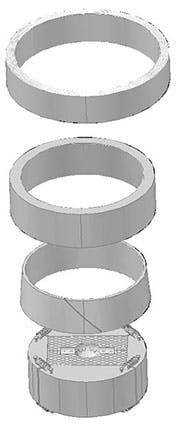
A simple design for the working fixture was retained. The central bar block is enclosed in a set of four jaws constrained by three concentric rings. The first two of these rings have corresponding conical surfaces, so that circumferential constraining stresses are generated by pressing axially the external collet on the internal one.
A third cylindrical element is added for security, hot mounted to develop interference fit upon cooling down.
In very special cases where objections could be raised to the fact that the standard means described above might be insufficient to contrast shattering forces developing in the die, two different solutions could be explored. The first alternative refers to special shapes of the bars providing an interlocking action; the second to external means to be employed to contain such forces.
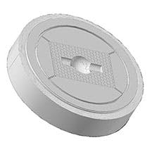
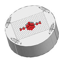
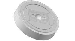
In the composite die example, the impression consists of half a sphere attached to two cylindrical axial sections. In Figure 1, showing an assembled composite die, some of the outermost bars were sectioned to present a continuous surface to the jaws, either between two opposite edges, or between the middle of two opposite faces.
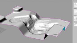
Figure 2 shows the composite die with an exploded view of the fixture, while Figure 3 is a precursor impression of the die showing an assembly arrangement.
Calculation Detail
In a typical forging case, the stresses developing in the constraining external ring must be determined in order to design adequately its dimensions, and to select properly the type of steel required. These calculations were kindly performed by Dr. David Barlam, a stress engineer, who applied finite element analysis (FEA) using MSC.Nastran and MSC.Patran software.
The additional hot-mounted constraining ring, designed to provide redundant safety and stability was excluded completely from this calculation.
The impression of the part to be forged, selected to simplify calculations, was a concentric cylindrical hole of 40-mm diameter and ~20-mm depth.
The ample radius at its base was meant to reduce local stress concentration: even so, it was found not negligible, but it is not influencing the resulting stresses in the constraining rings.
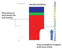
The forging pressure required was assumed to be 30 tons per square inch of the area of the item to be forged, about equivalent to 42 kg/sq. mm (Ref: ASM Metals Handbook, Vol. 5 - Forging and Casting - 1970, p.14, for a steel such as 4340.)
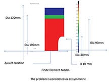
Slide 1 shows the configuration considered, representing half of a transversal section of the die. The horizontal axis in the slide corresponds to the die axis. The red colored area depicts the central part of the composite die. The typical remark, “The problem is considered axisymmetric,” is a simplifying assumption.
Half of the impression cavity section (appearing as white background in the bottom right of the slide) is limited by the horizontal axis, the border of the red area, and a virtual vertical line drawn from the red edge toward the bottom.
The diameters identify the assumptions selected to perform the calculation:
• 40 mm diameter of the circular impression
• 90 mm internal diameter of the internal ring
• 100 mm average of the external diameter of the internal ring, coinciding with the average internal diameter of the external ring
• 120 mm external diameter of the external ring.
Slide 2 shows the boundary condition:
• The left side represents the base of the die, to be placed on the forging press bed;
• The right side represents the top surface of the die that will meet the bottom side of the upper die during forging.
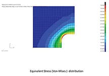
Slide 3 shows stress concentration of about 78 kg/sq. mm, ~111 ksi, ~765 MPa in the radius: not negligible, but inconsequential for this calculation.
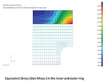
Slide 4 shows the maximum stress around the corner of the internal ring at about 6.8 kg/sq. mm, ~66.7 MPa, ~9.67 ksi.
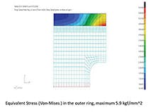
Slide 5 shows the maximum stress of about 5.9 kg/sq. mm, ~57.9 MPa, ~8.39 ksi in the external ring.
Both results are easily satisfied with any suitable construction steel.
Finally, this calculation demonstrates that in the example considered, the external ring can easily bear the maximum stress under forging. In any case, the outermost hot mounted ring, excluded totally from this calculation, should provide ample margin of stability for a long production run. Similar calculations should be conducted for any new composite die design, at least until sufficient experience is gathered.
Elia E. Levi is a mechanical engineer and an expert in welding process technologies, and prolific writer on those topics. For feedback and for further details not specified here, visit www.welding-advisers.com/Composite-Die-Description
